Ross Performance Parts Harmonic Dampers create an inter-molecular bond between the special formula rubber and the metal damper mass assembly achieving improved vibration damping and service life. All Ross Performance Parts harmonic dampers exceed ANDRA and SFI specifications.

Ross Tuffbond Metal Jacket
The Metal Jacket utilises the proprietary Ross Tuffbond elastomeric bonding process. This unit is designed with all of the original accessory pulley’s being utilised in the standard positions and sizing ratios. In some instances, the power steering pulley is slightly under driven to improve performance at high RPM, whilst not affecting low-speed drivability.
Metal Jacket dampers are designed for high-performance street and occasional track application.
Ross Tuffbond Race Series
The Race Series takes the proprietary Ross Tuffbond technology to another level.
The Race Series has a larger damper mass, lightweight pulley packs with under driven ratios and a separate damper hub. This high-level modular design allows for infinite variations for an array of applications. With the heart of the Ross Race Series having been developed over many years in conjunction with some of the leaders of the high-performance racing industry in their pursuit for excellence.
Ross Tuffbond Gold Series
With the number of genuine 1000HP race vehicles growing all the time, Ross Performance Parts is staying ahead of the game.
The Gold Series is based on the design principles of the Race Series, however, by using a dissimilar material (compared to your crank) for our damper hub, a Ross Performance Parts Gold Series damper will eliminate microscopic migration of material between the surfaces of the crank nose and damper hub. Our technology is pivotal to the prevention of galling and wear of the crankshaft – maintaining a secure press fit over the lifetime of the damper.
See also:
An engine must be lubricated for smooth, efficient performance, and an oiling system addresses this need. There are two main types of oiling systems, a wet sump and a dry sump.
The wet sump system is typical in most production cars, with the oil sitting in an oil pan reservoir stored beneath the crankshaft. An internal oil pump, which sucks the oil through a tube from the bottom of the pan’s sump, distributing oil throughout the engine. The wet sump system provides the advantage of a simple design, however there are potential issues regarding oil control particularly in modified engines and racing applications.
The large g-forces pulled under acceleration, aggressive braking and cornering at speed:
- cause the oil in the pan to gravitate away from the pumps pick-up tube, which will stave the system of oil and cause damage to the engine;
- cause the oil to slosh in the pan, creating a higher probability of the crankshaft slapping into the oil as it turns, whipping the oil into an aerated froth and reducing the oiling systems ability to create pressure; and
- each revolution of the crankshaft causes the parts to move rapidly through the oil and air in the pan, generating minute amounts of parasitic power loss caused by viscous drag and air drag (windage) negatively impacting horsepower
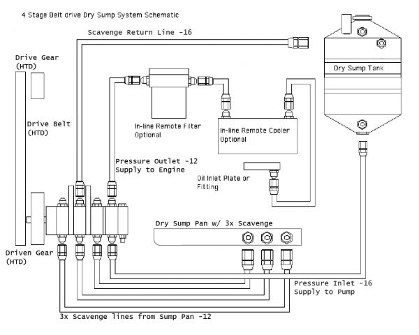
The alternative, a dry sump set-up, uses two or more oil pumps, and a separate oil reservoir. There are a minimum of two stages, one stage for pressure and at least one stage for scavenge. The pressure stage supplies oil from the bottom of the reservoir into the engine, and the scavenge stage/s remove oil out of the dry sump pan and return this oil (and air) to the reservoir, with the option for adding multiple scavenge stages to ensure maximum oil is scavenged from the engine. The reservoir (tank) controls the flow of oil, removing air bubbles, and sending the oil back to the oil pump to be routed through the engine.
In a dry sump set-up, the oil pump is usually mounted to the side of the engine, and driven by a belt off the front of the engine. It is typically lower than the reservoir, so it is gravity fed, rather than requiring a pump to suck the oil upward, as in the wet sump design, and performs more efficiently as it receives positive pressure on the suction side.
The dry sump set-up is more appropriate for a racing application, compared to the wet sump system, as it provides:
- improved reliability due to consistent oil pressure;
- the shallow oil pan allows the engine to be mounted lower in the chassis, effectively lowering the centre of gravity and provide flexibility to modify underfloor aerodynamics;
- the option to move the oil tank within the confines of the car to improve weight distribution;
- the option to increase oil capacity to be as large as you like;
- less chance of engine damage as no longer susceptible to starving the engine of oil due to movement issues caused by cornering or launching forces;
- protection against parasitic power loss as it keeps oil away from the crankshaft to reduce oil drag (viscous), and pulls out most the of air to reduce air drag (windage);
- cooler oil due to the external storage, plus additional cooling available by utilising an oil cooler, mounted inline between the pressure outlet and the engine; and
- easier maintenance, and replacement, as the pump is external to the engine.
The key documented disadvantage to a dry-sump setup is the added cost and complexity to your engine build, however, from the weekend enthusiast to the professional racer the significant advantages far out way the cost, remember no oil equals no engine!
Precision Trigger Systems are essential for high-performance engine tuning and ensuring your engine is delivering every horsepower within its capability.
The brain of the engine is the Engine Control Unit (ECU), it optimises engine performance by using sensors and triggers to identify exact engine timing to decide how to control certain actuators in an engine. The OEM ECU solution has limitations, as it is built for a price point and horsepower requirements, potentially sacrificing timing resolution and connectivity. An aftermarket ECU has more features for tunability and monitoring inputs, that most engines do not accommodate, to take full advantage of these capabilities a trigger system is required.
Triggering is one of the more complex areas of ECU configuration, and arguably the most important to get right. A trigger system relates to valve and crankshaft timing, providing crucial data to allow the engine to achieve optimal efficiency at a multitude of engine speeds. The trigger system provides mechanical triggers for the electronic sensors to read cam and crank timing.
A toothed trigger wheel is mounted to the harmonic damper and spins with the rotation of the crankshaft. The teeth pass a pickup sensor that sends a signal to the ECU indicating the rotational angle of the crankshaft. The ECU uses these sensors to monitor the relationship between the piston’s location and the valves’ positions, it learns how fast the engine is rotating and uses this data to precisely time the spark for the appropriate cylinder. In essence, a trigger system provides the critical link between an engine’s mechanical and electrical operations.
A correctly installed trigger system will allow the ECU to correctly sequence the timing, provide greater consistency with your engine tune and reduce the need for timing adjustments. An important note to remember is if you don’t measure you’re guessing.

Harmonic Dampers, also known as a crankshaft pulley, harmonic balancer, crankshaft damper, torsional damper or vibration damper, is a potentially confusing and often misunderstood part but is a critical component to your engine’s longevity and performance. It is not fitted to balance the engines rotating mass, but to control, or ‘dampen’, the engine harmonics created by torsional vibration.
Torsion is the twisting on an object due to an applied torque. At first glance, a stationary steel crank may appear rigid, however when sufficient force is created, for example, each time the crankshaft rotates and a cylinder fires, the crank bends, flexes and twists. Now consider, a piston comes to a dead stop twice per revolution, at the top and bottom of the cylinder, imagine how much force and impact that represents in an engine. These torsional vibrations, create resonance.
Every object has a natural frequency or resonance, an everyday example is a tuning fork. A tuning fork resonates at a natural frequency, and the sound that a particular tuning fork makes is directly related to the frequency that it is vibrating. Hitting a tuning fork harder will not change its sound, but it will increase the volume and duration of the vibration, amplifying its natural frequency. Prolonged amplification results in fatigue failure, essentially the object will vibrate itself to pieces. Similarly, a crankshaft has a frequency. The torsional vibrations, and resulting harmonics, greatly reduce the life of the crankshaft, bearings and associated componentry, or cause instantaneous failure if the crankshaft runs at or through an amplified resonance. In addition, other factors contribute to engine harmonics, including frequencies created by the speed of piston movement, timing chain slack, camshaft lobes and cylinder gas pressures.
A Harmonic Damper, is a device fitted to the nose of the crankshaft of an engine to absorb and dissipate the torsional crankshaft motion, and resulting harmonic vibrations, A correctly engineered, and fitted damper, has the ability to reduce the torsional stresses on the crank which handicap an engines horsepower potential. Whilst a harmonic damper will not add horsepower, the correct sized damper will allow the engine to run how it was designed to run, for the camshaft timing to stay stable, and the engine to live longer.